A continuous quest for the sails of the future
Since the setting up of Incidence Technologies in 2013, Incidence has an impressive unified design office and produces its own membranes. This capacity for analysis, testing and production has been a key offering and allows it to develop its own membranes, the D4, DFi® and the DF panel.
The Incidence Technologies team is working to further optimise D4, DFi® and the recent DF panel: increasing weight or flexibility, maintaining the required shape and durability.
It is a real background research work that is based on aerodynamics and finite elements modelling software, with wind tunnel testing … These studies and analyses enable them to project the sails of the future.

Benchmark figures
Creation in 2013
Number one Producer of filamentary membranes in Europe.
2300 m2 of membranes produced every month.
A R&D office dedicated to the development of membranes
Computing capacity : Panel code and RANS (Reynolds Average Navier Stokes)
One production unit for D4®, DFi®, DFi FIT®
Numerical calculations of Incidence Technologies are performance-support tools for sailors
Incidence is one of the few sailmakers to offer advanced numerical studies FSI (Fluid Structure Interaction) thanks to two different types of calculation: panel code and RANS (Reynolds Average Navier Stokes*).Both are valuable performance tools for offshore racing teams.
The Incidence Technologies’ R&D team and design office’s skill and ability with these tools allow them to not only design sails which are “high performance and set correctly from the very first test”, but also to provide valuable data to offshore racing teams and naval architects.
Strong performance support
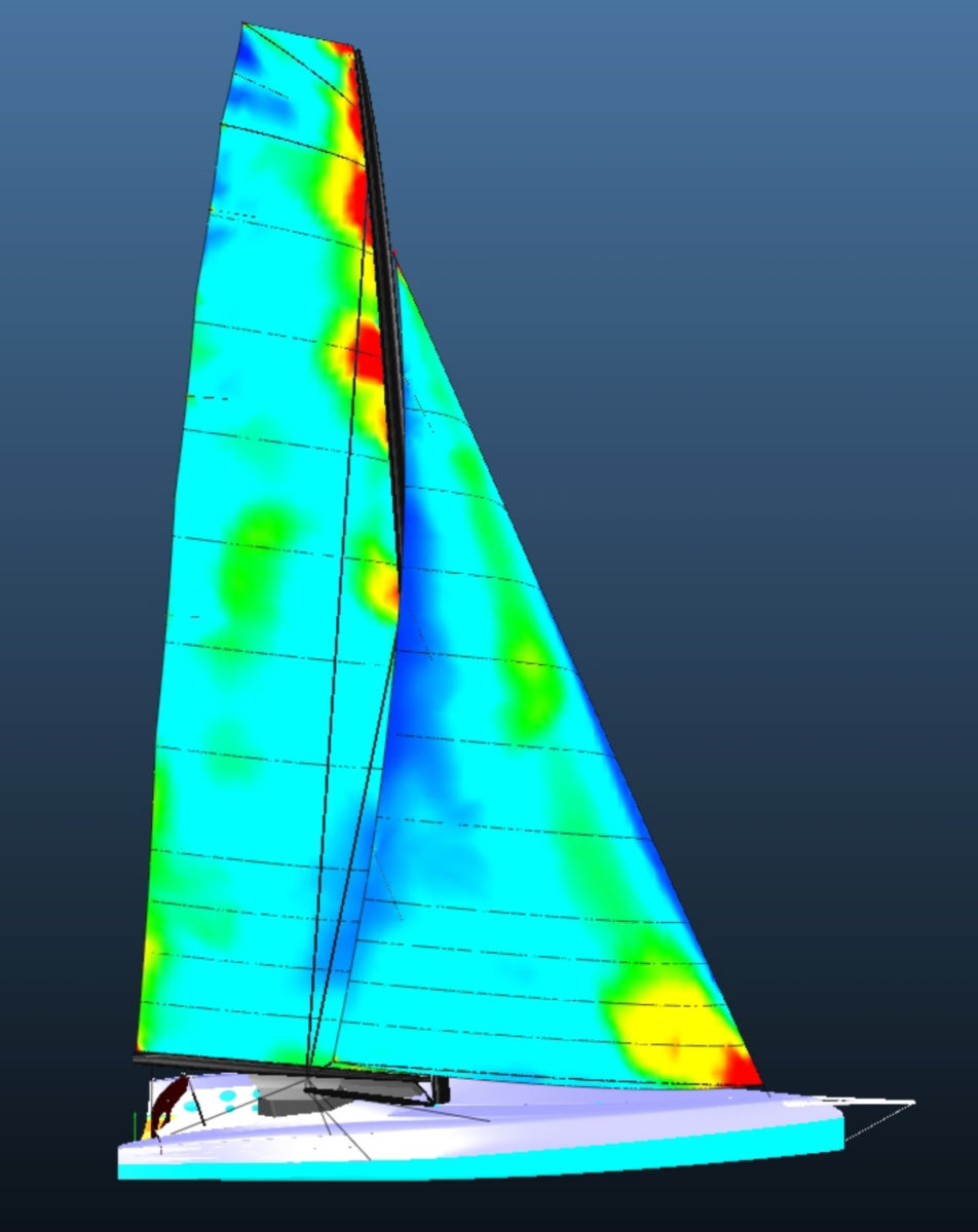
The FSI numerical calculations are used to calculate the different loads of the rigging, to optimise sail profiles, or to obtain the aerodynamic matrix of the boat (a 3D map of the forces exerted on the boat).
All of this work is carried out in close collaboration with naval architects. The decision to use panel code or RANS calculations is dependant on the project specifications, the completion deadline and/or the budget allocated to the study.
The perfect sail
Incidence Sails’ engineers and designers are able to use an iterative technique with RANS calculations. This method takes into account the fluidity and turbulence of the air flows on the inner and outer surfaces of the sails.
At the end of this rather complex process (see details below), the profile that’s drawn is perfectly optimized and in line with the initial specifications: a major time saver for offshore racing teams.

“The profiles fall right in place. They are perfect. There were no round trips to the sail-loft. This is a huge time saver for us “, Sébastien Simon, skipper of IMOCA Arkéa – Paprec, fully equipped with Incidence Sails.
“I am very happy with my set of sails, I didin’t have to go back, not even once, to the sail-loft for modifications“, Fabien Delahaye, skipper of Figaro Loubsol, also fully equipped with Incidence Sails.
Determining the fastest trajectory
Hydrodynamic data from the naval architects and aerodynamic calculations performed at Incidence Technologies fine-tune the polars and the creation of the VPP (Velocty Prediction Program). Together, these VPPs represent all of the boat’s virtual polars according to all the sail configurations and the different settings for the rigging, foils, etc.
With a complete VPP, combined with routing statistics for a given route, it is possible to determine the fastest trajectory and the most efficient sail combinations for this layout.
In summary, whether it comes to a simple load calculation or the development of an aerodynamic matrix for a VPP, the Incidence Technologies’ Team provides offshore racing teams and naval architects with all the data they need to optimize their performance.
* Navier-Stokes
In fluid mechanics, the Navier–Stokes equations are non-linear, partial derivative equations which describe the movement of Newtonian fuids (gaz, liquids). They are useful because they describe the physics of many phenomena of scientific and engineering interest. They can be used to model the weather, ocean currents, water flow in a pipe and air flow around a wing.The Navier–Stokes equations, in their full and simplified forms, help with the design of aircraft and cars, the study of blood flow, the design of power stations, the analysis of pollution, and many other things…
The Navier–Stokes equations are named after two scientists of the 19e century : the mathematician and Canal and Port Engineer Claude-Louis Navier who was the first person to introduce the idea of viscosity in Euler équations in 1823 and the physician George Gabriel Stokes, who first derived the expression for drag force.
Details on the different kinds of calculations performed by Incidence
Structural load calculation
The structural load calculation helps determine the hardware for the boat. Basic data is collected, generally concerning the maximum loads that the rigging and sails can handle. The calculations are done in panel code.
Optimisation of Flying Shapes
In order to optimise a sail profile, designers at Incidence aim to create the maximum thrust forces from the sail, while reducing the heeling moment.
Optimisation of the sails’ structure
Optimising the structure of the sail helps to optimise the quantity of materials and the orientation of the fibers according to how the sail changes shape when sailing. This is achieved by improving the distribution of fibres (D4) or fibre strips (DFi®; DFi FIT®), without weighing down the sail.
Aerodynamic Matrix
–Aerodynamic matrix obtained with pannel code
Incidence Technologies software uses panel code, a calculation method in which the flow is considered to be “non-viscous”, “irrotational” and incompressible (in upwind sailing conditions, when the flow is “attached” to the sails).
The data that’s obtained is used to model the approximate first profile and its aerodynamic data.
When the apparent wind angle (AWA) becomes too large (greater than 35 °), panel code no longer gives precise results, since it does not take into account the stall of the fluid (air flow) on the sail. It is therefore more relevant to continue the calculation with RANS iterations.
–Aerodynamic matrix obtained with RANS iteration
«The RANS method consists of modeling the movement of a Newtonian fluid by taking into account turbulence and fluctuation. With this method we are able to obtain precise data whatever the apparent wind angle», explains Pierre-Antoine Morvan in charge of development at Incidence Technologies.
Thanks to RANS modeling, Incidence can include the aerodynamic elements of the hull and deck, in order to take them into account in the design of its sails.
2020 innovation
The Strong Luff : versatility and higher speed
New cable less technology
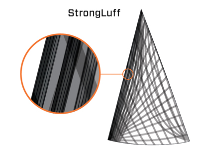
The Strong Luff technology developped by the R&D Team working at Incidence Group and designed by the skilled hands working in the sail-loft, is a new cable-less technology made for DFi® headsails.
The main advantage of Strong Luff is to allow a straighter luff and higher performance. Explanations…
This comes from the structure of the sails composed by filamentary membranes : the filaments are placed along the luff from the tack to the head.
This new cable-less technology reinforces the luff and has great advantages :
- It increases the performance of the sail thanks to a greater ease of use and a reduced sag.
- The sail is also lighter.

This is a first!
Incidence is the first sailmaker to develop this technique of pre-impregnated continuous filaments on more than 30 meters. This is made possible by the equipments and the size of The Incidence sail-loft.
The continuity between the tack and the head distinguishes the Strong Luff from any other cable-less system.

Lalou Roucayrol
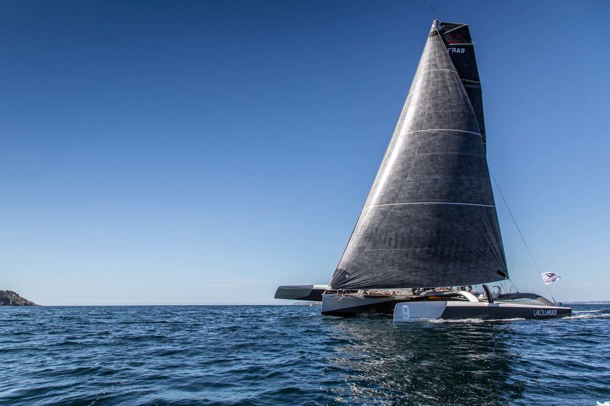
« I have always been confident with the Sailmaker Incidence and very satisfied with the innovations they offer. It has always improved overall performance, therefore we didn’t hesitate to try this new Strong Luff gennaker.
The 2018 Gennaker was really great, this new sail needs another kind of understanding. We have had to learn to adjust the sails as we could adjust the luff : we clearly benefit from it.
During the 3 races (Grand Prix Valdys in Douarnenez, Trophée des Multicoques in the Bay of Saint-Brieuc and the Grand Prix Brest Multi50) we have been able to do some testing under all weather and sea state conditions : the improvement in terms of performance and versatility is amazing !
The settings are much more sensitive and dynamic thanks to the Strong Luff along with the stiffness of the DFI®. It allows quicker accelarations. We had the nicest sails amongst the fleet »
Quentin Vlamynk
« We needed a new gennaker that we could keep for the two upcoming racing seasons. Incidence offered us to test their new cable-less technology. It’s a real bonus : Furling the sail is getting faster, the leading edge is thinner, the sail remains flat, with a homogeneous draft. We slightly work on the tack and the luff. The gain in boatspeed is impressive
Horizontal wrinkels on the luff are removed as it is directly connected to the fibre filaments. We have ordered a J3 Strong Luff for the upcoming season. The materials, the DFI® and the DFI FIT® are always efficient.
With each set of sails, it’s getting better ! »
The manufacturing secrets of Incidence membranes
Like all membranes manufactured by Incidence Technologies, is designed internally in France (next to La Rochelle).
7 bar pressure lamination
These membranes are hot-pressed at approximately 7 bars of pressure. Tests conducted at Incidence Technologies have shown that a membrane laminated at 7 bars is 30% thinner and 23% more tear-resistant* than a membrane laminated only under vacuum (with 1 bar of pressure).
*This tear test assesses the adhesion between the fibers and the resin, thus evaluating the quality of the lamination.
Without scrim: same resistance, more lightness
The membranes produced by Incidence Technologies are designed without assembly grid called “scrim” (polyester fibres grid facilitating the laying of plugs during the membrane manufacturing).
Others test*, also carried out by Incidence Technologies, have shown that the scrim does not increase membrane tearing resistance. And it increases the material’s weight by 10% to 25% (depending on the final weight of the membrane).
* This tearing test consists in testing the bonding between the fibres and the resin, in other words the lamination quality.
Tableau des fibres
| Performance | Durability | ||||||
| Robustness | Module | Shape holding capacity |
Assessment | Flexion resistance* |
UV resistance** | Bilan | |
| cN/dTex | cN/dTex | comment | rating/10 | loss % | month | rating/10 | |
| Aramid | 21,4 | 813 | correct | 9 | 25 | 2 | 7 |
| Dyneema | 35,1 | 1160 | medium | 6 | 0 | 7 | 10 |
| FIT | 29 | 1050 | very good | 9,5 | 2 | 1 | 9 |
| Vectran | 28 | 654 | very good | 8 | 2 | 1 | 9 |
| Carbon | 33 | 1578 | very good | 10 | 100 | infinite | 1 |
| PEN | 8 | 187 | correct | 3 | 0 | 6 | 9 |
| Polyester | 10 | 77 | correct | 2 | 0 | 6 | 9 |
| Nylon | 9,5 | 45 | correct | 1 | 0 | 3 | 5 |
* 60 flexions at 90°
** time for module/2
Robustness = tearing
Module = force to inflict a deformation
Shape holding = shape holding in time


